
Vehicle LED Lighting
LEDs are becoming standard features among a lot of vehicles. Doing full vehicle LED swaps are very common for a lot of people who want to have better night visibility and improve overall aesthetics.
In this series of projects, I have fitted different types of LEDs to my vehicle including LED light bars, turn signals, daytime running lights, and additional side markers.
Silverado Windshield Light Bar
There are two objectives that I want to achieve for this modification.
Hard mount the light bar at the top of the windshield
Install remote control on the light bar
Installing Process
The Lightbar is mounted on two vehicle-specific brackets on the A pillar. To keep the two brackets parallel to each other, I used a tape measure, level, and markers to position the brackets on each side.
There are three mounting holes for each bracket. When I marked up the position on the A pillar, I drilled out the mounting holes for the bracket.
The brackets came painted, but the paint is regular metal paint. While the regular metal paint is fine, considering the vehicle is mainly parked outside, I want to make the bracket weatherproof. I sanded the paint on the bracket off using a sander. Then I used rubber-based spray paint to paint the brackets.
After the brackets dried, I put up rubber seal pads between the bracket and the vehicle A pillar. Then I used a rivet gun to install the brackets on the A pillar and mounted the light bar onto the brackets.

The wire of the lightbar has been routed on the passenger side. I used the gap between the A pillar and the windshield to route the wire to the engine bay. The wire uses 12v to power, so I tested the light bar by directly connecting them to a spare 12v battery. The light bar is functional.
After the initial test, I connected the wire to a LED Light Bar Remote Wiring Harness.

I followed the schematics provided by the module manufacturer to wire up the light bar and connect it to the battery.

Result
After the installation, the light bar is functional with remote control.
Silverado Full LED Vehicle Lighting
This modification aimed to change all the vehicle lighting from incandescent bulbs to LED. The current default incandescent bulbs have very low light output. For added safety when driving in bad weather condition, I replaced all the incandescent bulbs with LEDs that includes the headlights (Low Beam, High Beam, Turn signal & Fog lights), Backlights (Break light, turn signal & Reverse lights), and Third Brake light (Break light & Cargo Lamp)
The advantages of LED lighting are
Long lifespan
High light output
Low heat
After some initial research, I found out that there is a major problem that I need to address during the installation. By default, the vehicle’s BCM will read the voltage of the incandescent bulbs to determine if it is functional or not. When the LEDs are installed, due to the LEDs' low impedance/current draw, the BCM will determine that the LED lights are below the reference working voltage, so there will be an error message on the vehicle instrument cluster.
There are two ways that I can approach this problem.
The first way is to splice the lighting circuit and add resistors to each LED bulb. While the advantage of this method is easy execution, there are extra components that I need to add to the circuit, which is not safe for the overall electrical system. Also, I need to screw down the resistors to the vehicle body because the resistors are very hot while operating, and I cannot tape them to the plastic housing of the light assembly.
The second way is to disable or change the safety value of the BCM program. The challenge for this method is finding GM-authorized shops to unlock the BCM program to let me reprogram it.
I eventually chose the second method because it is more OEM style, and I do not need to add additional circuitry to the vehicle.
The first thing I did was disassemble the front part of the vehicle, which includes the front bumper and front grille. This will give me more room to work on the headlights and clean up and weather seal all the wires in the system.

The second step is to pull out all the current incandescent bulbs from the light assembly. And then replace them with LED lights below.

As I expected, when all the LED lights are installed, the vehicle is indicating lightbulb failure.
I asked an online service to unlock my BCM so I could get access to more detailed programming of vehicle lighting.
I used the web system provided and the ACDelco Service Programming System (SPS2) on a Windows laptop to change the detail values for all the lights.


After changing the value of the outage detection value from 5 amp down to 0.25 amp, I flash the BCM with the modified program to the vehicle.
Before I assembled all the parts back to the vehicle, I started the vehicle and tested the low beam, high beam, fog light, brake light, reverse light, turn signal, emergency light, and cargo lamp to ensure all the lights were working and flashing at the DOT complied rates. I also put in a known faulty LED light bulb to test if the BCM outage detection level is correct. The vehicle can detect the fault LED.
In the end, I adjusted the headlights aiming in front of a white wall with a tape measure and assembled the vehicle.
Result
With the modified value in the BCM, the vehicle has no error reported while all LEDs are working. There are no other errors that occur due to the BCM reprogram. With the reprogrammed BCM, the vehicle passed the Massachusetts state inspection.
Bronco Sport Vehicle Side Turn Signal
The purpose of this modification is to allocate the existing decorative panel at the front sides of the vehicle to install LED turn signals to improve signal visibility at all angles for the vehicle.
There are two things to check for this modification. The first thing is to check the turn signal wire for the front headlamp. The second thing is to check whether splicing the turn signal wire will cause malfunction of the front turn signal lights.
When checking the front turn signal line, I managed to acquire the schematics for the front turn signal wiring.


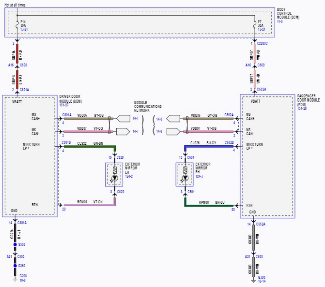
Based on the schematics, the left turn signal wire is the blue one and the right turn signal wire is the yellow one.
I used Forscan and ELM 327 cable to check the body control module to see if there are any turning signal outage warnings turn on. Upon testing with a multimeter, the existing harness will not malfunction when tapping on additional wires. The body control module CANbus data shows that the vehicle has already have LED headlamps so it will not have an outage warning like regular incandescent bulbs.
I acquired a set of side marker LED lights on Amazon, these lights are an exact fit for my vehicle.

The LED part only has positive and negative, so I will tap the wires to the existing headlamp harness.
There are four ways I can tap the wires into the harness. The first way is to use a T-tap connector to snap on the wire. The advantage of this method is it easy and fast to install, however, the disadvantage is the T tap is not waterproof, and there will be potential shorting in long-term use.
The second way is to splice the existing harness wire and combine the harness wire with the led wire to get power. The advantage of this method is it can be weatherproofed by using electrical tape, but the disadvantage is the wiring will not look very good.
The third method is to solder the wire to the existing wire, the advantage of this method is it will be a very secure fit and weatherproofing is easy to apply. The disadvantage of this is it requires more time to work on and possible danger to melt the harness wire.
The fourth method is to take apart the harness and clamp the new wire to the existing harness. The advantage of this method is it will be the best way to add wires to existing wiring, the disadvantage is I need to take apart the whole harness and reassemble it again.
I initially chose to take apart the harness and add it directly to the plug, but after some test fit, the plug can only fit on cable per position, so I cannot add a wire in. So later I chose to solder the wire onto the existing cables.
I took off the headlamp harness from the headlamp and strip a part of the harness cable to make room for the soldering. After soldering all the wires. I used 3M super 88 electrical tapes to cover up the soldering joints, and then I use automotive harness cloth tape to wrap all the wires with the existing harness to protect the cable.

Result

After two weeks of testing, the side markers are working in great condition without any error. I tested with turn signals and emergency lights, they are all in good working condition.