
Adaptive Cruise Control
Adaptive Cruise control are now standard features on many new vehicles, but some are still optional features that can be purchase as add-onwhen ordering the vehicle. Adaptive Cruise Control assist the driver to maintain a set following distance, lane centering and pre-collision mitigation.
In this project I added Adaptive Cruise Control to my vehicle which do not comes with the add-on safety package.
Ford C2 Platform Adaptive Cruise Control Retrofit
Bronco Sport all trims offer the optional Ford CoPilot 360+ Assist package. The Ford CoPilot 360+ Assist is an L2 Autonomous driving system that includes navigation, adaptive cruise control, lane centering, traffic sign recognition, pre-collision mitigation by braking, and evasive steering. The vehicle without this package will only have L1 Autonomous driving with regular cruise control.
Due to the current production delay, most of the dealer-ordered models are not equipped with the Ford CoPilot 360+ Assist package. Especially with my trim, Bronco Sport Badlands, according to online production information, in order to get Ford CoPilot 360+ Assist equipped Bronco Sport Badlands, the waiting time exceeded 6 months.
Before I start the installation and programming, I acquired the vehicle wiring diagram and platform CAD file. I also took apart the front bumper assembly to inspect the wiring path in order to determine the parts I need.
First I acquired the system diagram for the Image Processing Module A (IPMA) The Millimeter-wave sensor directly communicates with the IPMA on CANbus.

According to the diagram, I need to establish a connection between the sensor and the IPMA.
Below is an electrical wiring diagram of the engine compartment.

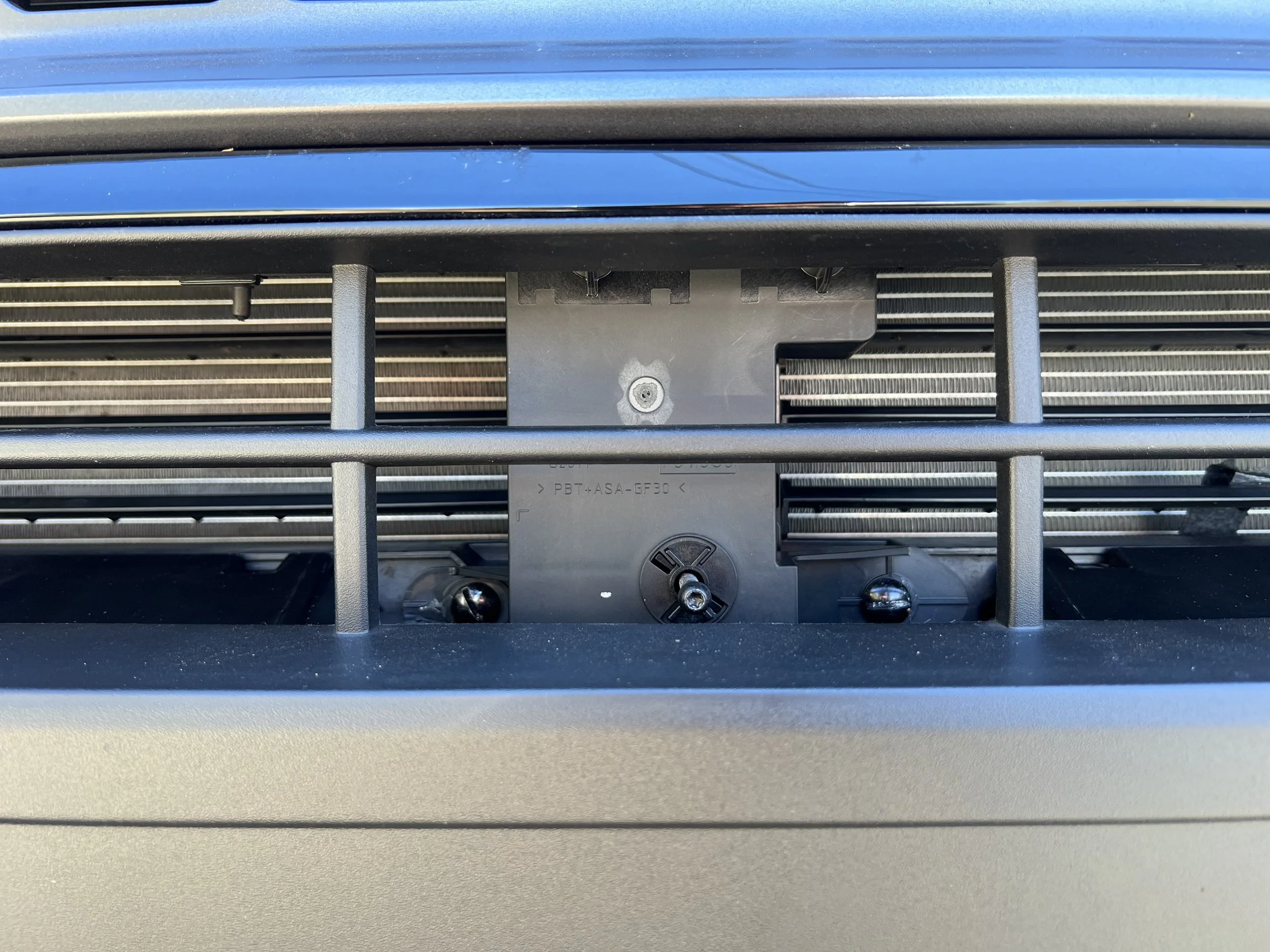
Upon inspecting, the wire that connects the millimeter wave radar sensor to the harness assembly is 14290A. However, with my visual inspection, my vehicle does not have the connector for 14290A on 12A522.
With some further wire tracing, in order to change Harness 12A522, I also need to take apart the front radiator to fully remove the harness. Since I don’t have the equipment to take apart the radiator assembly. I chose to make my own harness for the MM wave sensor.

I acquired a MM wave sensor from a wrecked Ford Explorer, the same MM wave sensor used on my vehicle. I also acquired a new sensor bracket and sensor cover. A new bracket will ensure a correct fit, which is important for the sensor calibration later.
There are several different configurations of the sensor, but they can all be programmed
I purchased 20 AWG automotive wires, 22AWG CANbus wires, automotive cloth tape, electrical tape, and protective wire tubes for making the harness.
According to this MM wave sensor pigtail diagram

I used CANbus Wire to connect #3 CAN High and #2 CAN low. Then I used a 20AWG wire to connect power on #1 and #4.
With the pigtail wiring done, I waterproofed the wire and route it through the firewall to reach the vehicle cabin.
At this stage, the two CANbus wires need to reach the IPMA on the windshield behind the rear mirror. I connected the CAN High and CAN Low by splicing them into the IPMA plug at #3 and #11.

For the power delivery, I tied in the sensor wire to the fuse panel.
With all the wiring done, I turned on the vehicle to check if the system detect the new unit. When the ignition is on, the cluster shows the message “Front Sensor Adjustment required.” That means the IPMA is able to establish a connection with the MM wave sensor at the front of the vehicle. The sensor now needs additional programming and physical calibration once everything is installed.
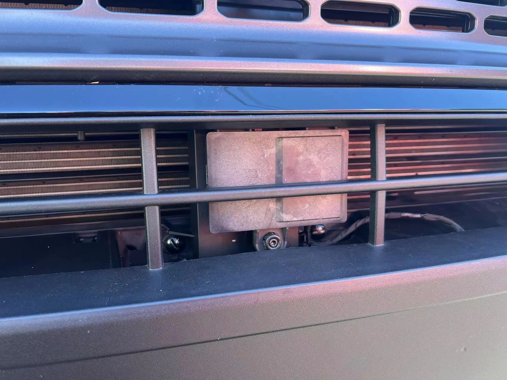
I cut out the front facia of the radiator bracket and expose the mounting points for the sensor bracket.
Then I installed the MM wave sensor on the bracket and used a spirit level to calibrate the angle of the MM wave sensor.
After putting all the panels back, route the wire to the engine compartment. I moved to the steering wheel to replace the control switch.
I disconnected the battery again because, in order to change the steering wheel control switch, I need to take off the airbag. When the vehicle has power, there might be a risk to trigger the airbag to deploy.
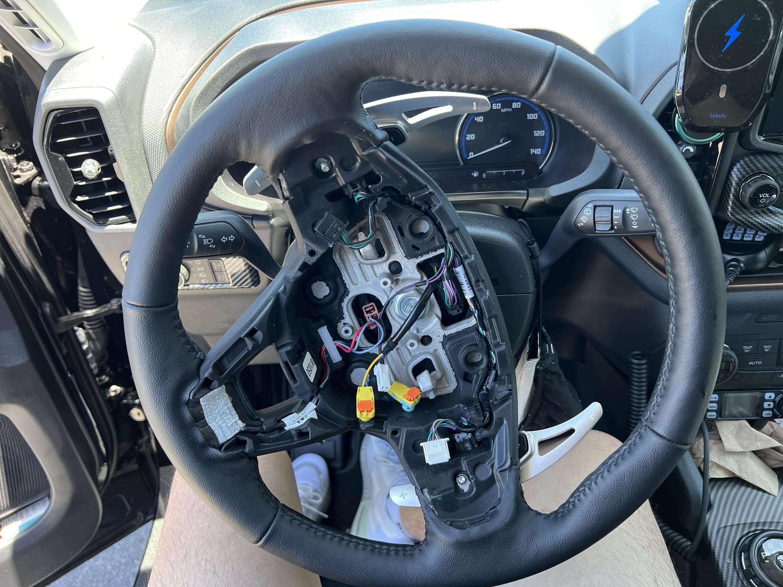

I switched out the regular cruise control switch to the adaptive cruise control switch.

Upon putting back the steering wheel assembly, connect the battery. I checked if the vehicle can be turned on and closed up all the panels. After this step, all the physical modification of this project is done.
In order to make the Adaptive cruise control work, the Image Processing Unit (IPMA), Cruise Control Module (CCM), ABS, Steering Column Control Module (SCCM), Instrument Panel Cluster (IPC), Body Control Module (BCM), and Human Machine Interface Module(APIM) all need to be reprogrammed.
I used a test version of Forscan software provided by the Forscan team to do the reprogramming.
First, on the High-Speed CANbus, I accessed the BCM to change the vehicle cruise control protocol to “Adaptive Cruise Control.” Then in APIM, I added “Adaptive Cruise Control, Intelligent Adaptive Cruise Control, Traffic Sign Recognition, Evasive Steering, Pre-Collision Brake Mitigation” to the Driver Assist section.
After the BCM and APIM reprogram, I switched to Mid Speed CANbus to program the rest of the modules. Starting with IPC, The visualization of the adaptive cruise control is shown on the instrument cluster, So I enabled the traffic sign recognition and adaptive cruise control panel on the Cluster Screen.
Then I need to program the CCM. Since the MM wave sensor comes from a Ford Explorer, I need to change the vehicle VIN and Vehicle model to the CCM.
The VIN number on the vehicle is in ASCII but CANbus recognize hexadecimal codes. I converted my VIN number to hexadecimal. This will establish a correct connection with IPMA, IPC and ABS since all of these modules use VIN to cross-check the integrity of the system.
In IPMA, I reprogrammed the cruise control function, traffic sign recognition, lane centering, distance alert, and pre-collision mitigation.

My vehicle does not come with factory navigation, I used the camera on the IPMA for traffic sign recognition. The recognition data will be a reference for the intelligent adaptive cruise control to adjust the vehicle speed.
Since I changed the steering wheel switch, the programming of SCCM needs to be altered in order to recognize the new switch. I wrote the new program to the SCCM to establish a connection with the new switch. The last programming step is for the ABS.

My vehicle does not come with Adaptive cruise control, so the ABS pump is a regular vacuum-boosted pump rather than an electric boosted pump. The electric booster pump will initiate smoother braking when the vehicle is on adaptive cruise control in the city. While the vacuum-boosted pump will have stepped braking applied at each stop. But it will only be noticeable when using Adaptive Cruise Control in Stop & Go traffic. Both pumps are able to function with the adaptive cruise control without any safety concerns.
I reprogrammed the ABS for the Adaptive Cruise Control function.
With all the programming done, the vehicle is now capable of doing Adaptive Cruise Control at L2 Autonomous driving. The last step is to calibrate the front sensor.
The calibration will let the MM wave sensor and Camera collect data to establish its angle and sensitivity. In this process, I used the dev version of the Forscan to do the calibration.
I did the calibration early in the morning on a straight road where there is no excessive traffic. The calibration will require the vehicle to move at a constant speed above 30 mph. And there will be minimum metal objects like metal billboards on the side of the road.
I finished the calibration in 15 minutes with both the sensor and camera calibrated.
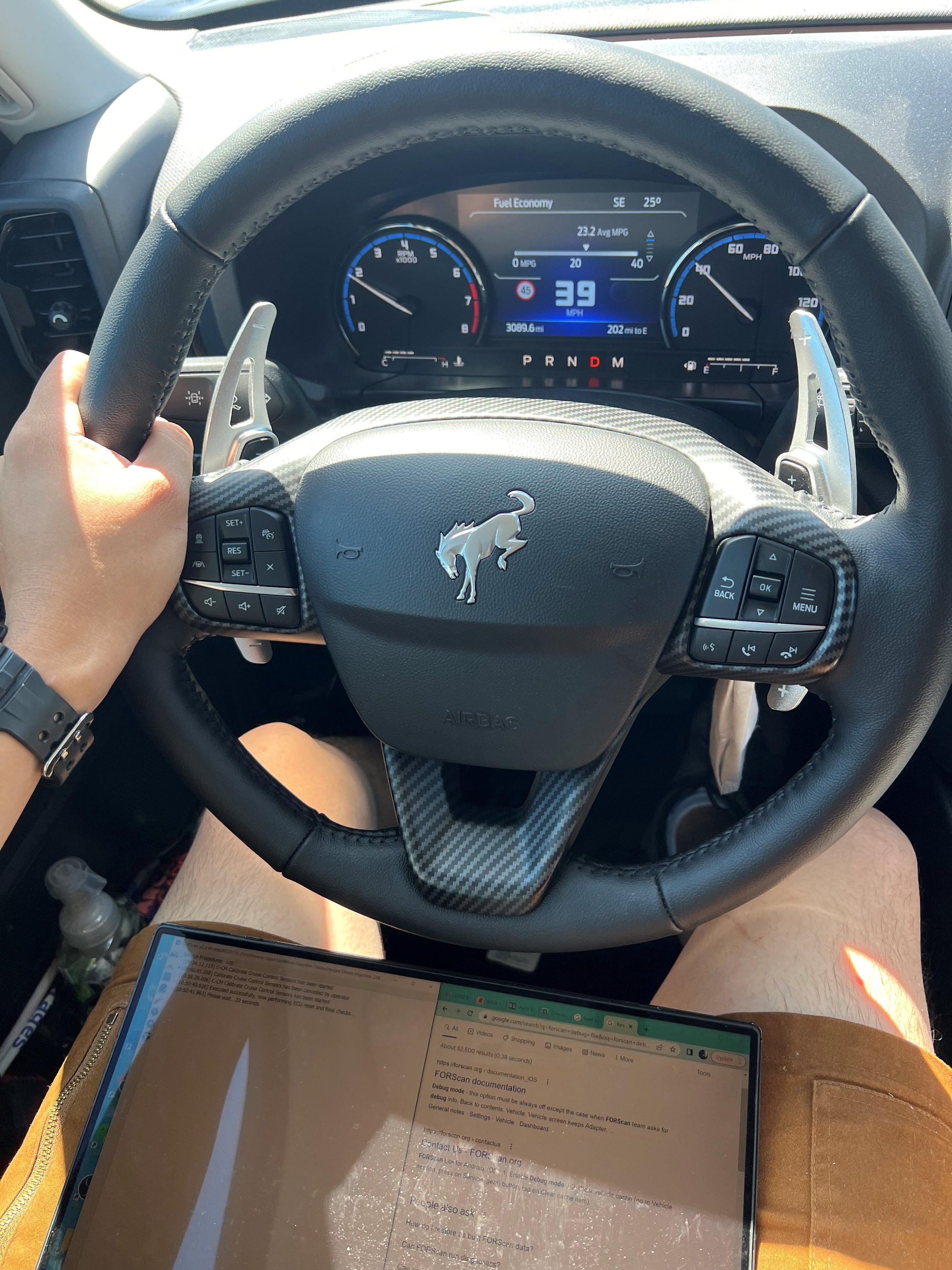
After the calibration, the Adaptive Cruise Control is now in working condition
Result
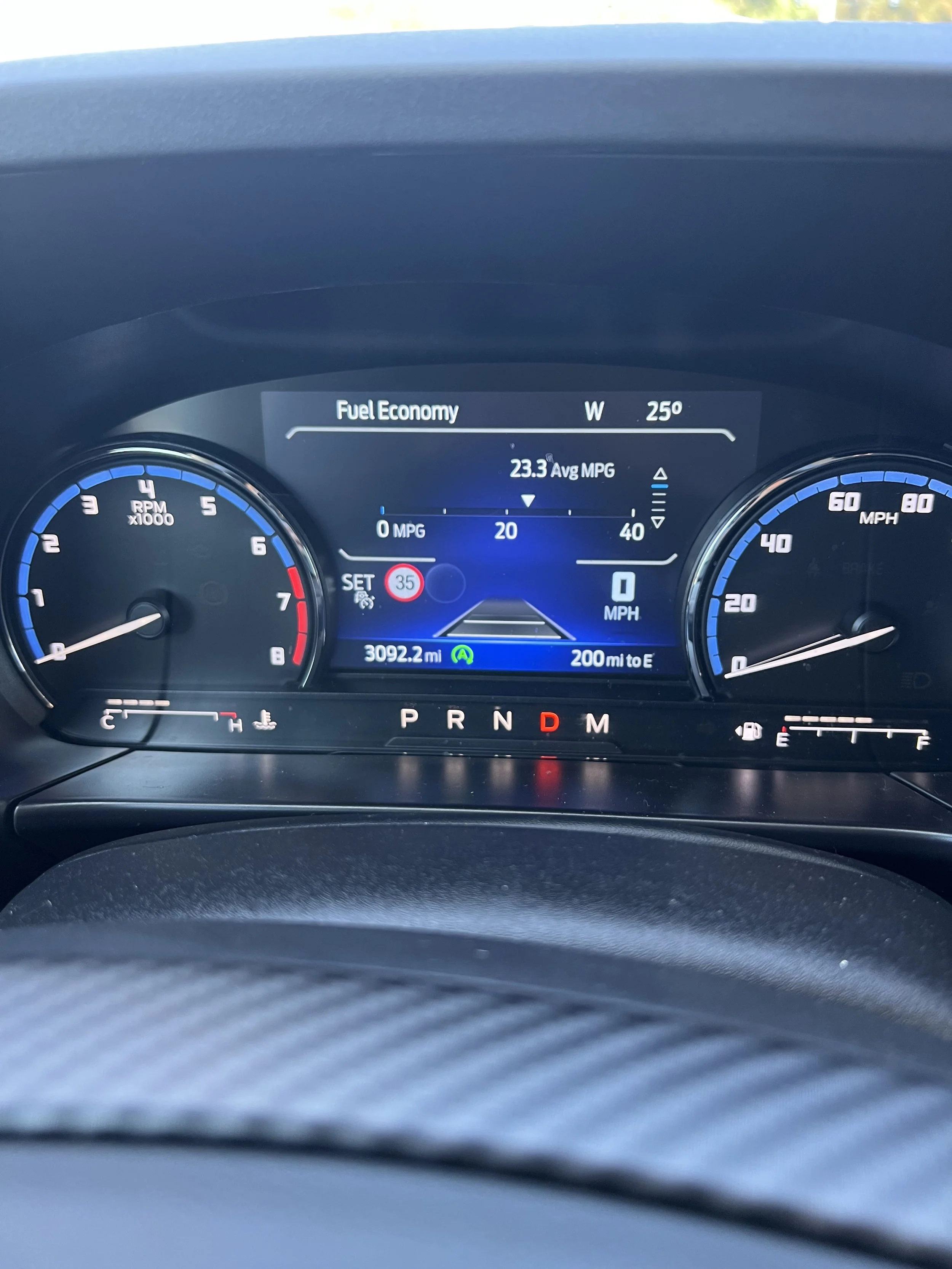
After 100 miles of testing on both highways and city roads. The Adaptive Cruise Control is functioning as expected. There are no DTC codes present. The Traffic sign recognition data can be displayed and unitized by the Adaptive Cruise Control system to adjust the vehicle speed. In city scenarios, the vehicle is able to make full stops behind other vehicles at a safe distance.
I am not able to test pre-collision brake mitigation with other vehicles because it is not safe to do it. However, I used a cardboard box to test the function on a closed road with no foot traffic or vehicle traffic. The vehicle is able to detect the obstacle, warn the driver, and apply brakes before the collision.